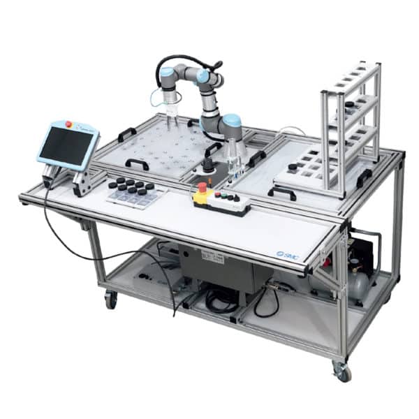
Description
Features
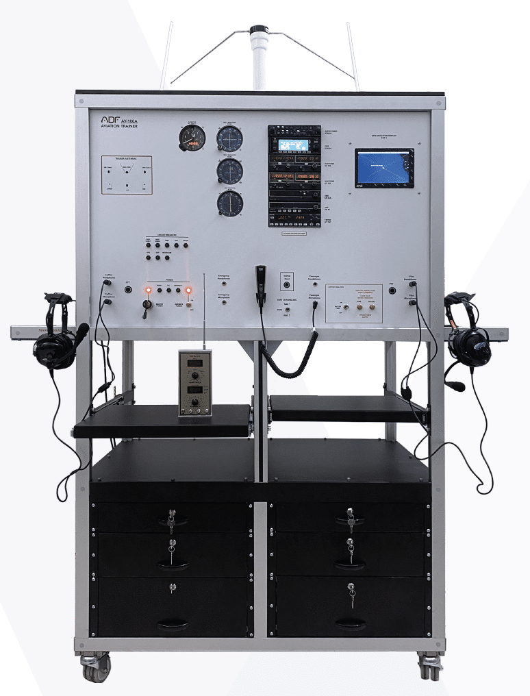
- The system combine “Navigation(ADF-DME-VOR-ILS-GPS-XPDR) instrumentation”, “Communication(VHF) instrumentation”, and “navigational information”.
- NAV system testing
- Comm System Testing
- Indication Testing
- Encoder Altimeter Testing
- Altitude simulation
- Altimeter and Transponder run in sync
- TXPDR Ident • DME Channel selection
- 6(six) metal drawers.
- All required cabling, coupler ,splitter and socket
- Instructor’s Panel for fault insertion.
- Extension cable for GPS Antenna
- Tripod stand for mounting GPS Antenna
- The system mounted on a metal/aluminum mobile stand.
- Metal/aluminum frame with 4 wheels. 2 of 4 wheels are lockable
- Training video for teachers
- Delivered fully assembled tested and ready to operate
Components
- Two(2) pieces Nav/Com Radio ( Vor/ ILS )
- Two(2) pieces Nav Indicators ( Analog or Digital )
- GPS (Global Positioning System )
- ADF (Automatic Direction Finder )
- ADF Indicator • ILS (Instrument Landing System )
- DME (Distance Measuring Equipment)
- Transponder • Marker Beacon
- Altitude Encoder
- Intercom System
- Two Pilot Headsets
- Dynamic Microphone
- Altimeter
- Vacuum Pump
- Dc Power Box
- Circuit Breaker
- Antennas
- VOR/LOC antenna
- ADF antenna
- Marker-Beacon antenna
- GS antenna
- VHF-COM antenna (2 pieces)
- TRANSPONDER antenna
- All antennas cables
Component Technical Specs
- NAV/COMM Transceiver
- 200-channel NAV receiver
- Built-in VOR Converter
- Maksimum 25 kHz channel spacing
- Frequency(COM) 118.000 to 136.975
- Nav frequency 108.00 MHz to 117.95 MHz in 50 kHz spacing
- VOR/LOC converter
- Input voltage 28 VDC
- Built-in VOR/Localizer converter
- flip-flop frequencies
- Volume control
- Frequency memory and recall
- Display
- Frequency stability: ±0.0015%
- Original installation manual.


