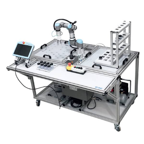
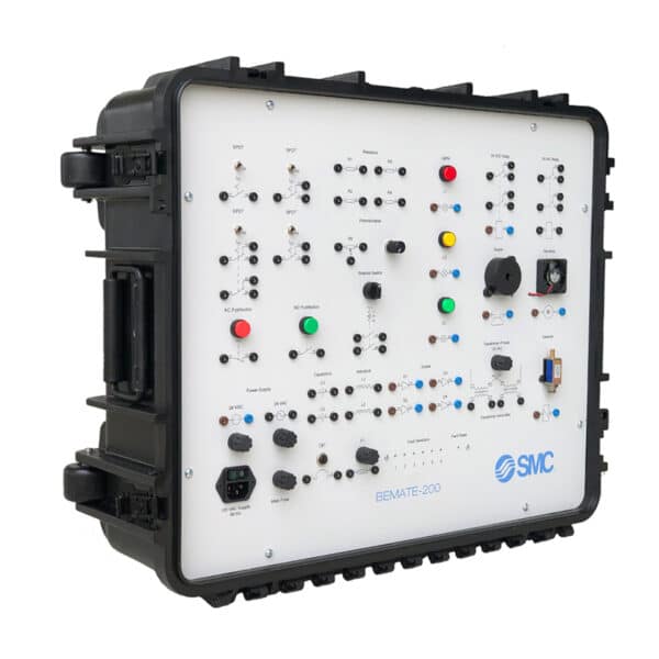
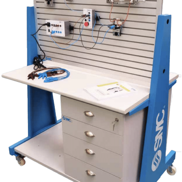
Description
Features
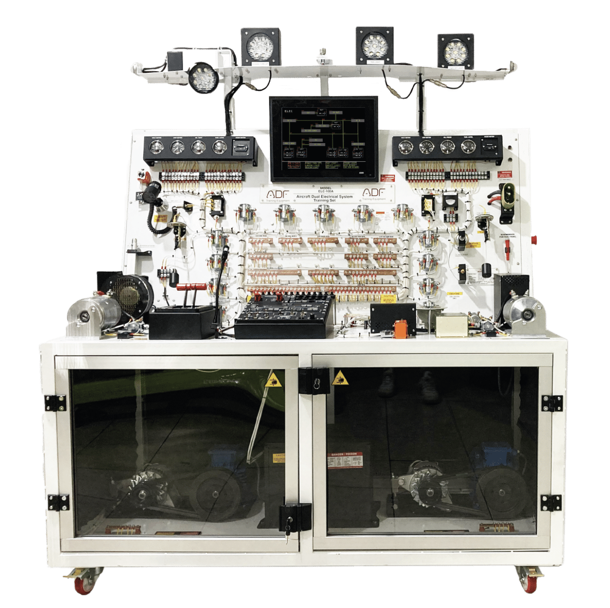
- Understanding fundamentals of aircraft Electrical Systems and its components
- Typical aircraft Dual Electrical System system.
- Instructor’s fault panel for introduction to troubleshooting (10 simulated faults)
- Typical Cockpit Instrumentation, Circuit Breakers, and Controls
- Digital Instrument Panel (ECAM) System
- Analog Instruments
- DC and AC powers
- Representative DC and AC Loads
- AC and DC bus system (Main, Auxiliary, Bus, Gen, AC, Avionics)
- Internal and External Lights
- Split bus system
- Battery charging system
- Distribution terminal strip
- The system mounted on a metal/aluminum mobile stand.
- Metal/aluminum frame with 4 wheels. 2 of 4 wheels are lockable.
- Training video for teachers
- Delivered fully assembled tested and ready to operate
- Colored Ultraviolet printing method on aliminium compozit panel.
- Generators and battery should be in a box under the trainer with transparent plexiglass in front.
- All components should be connected via terminals.
- Computer Control Software (CCS)
- Trainer monitored Fault panel control from software
- All data shown in the software
Components
- Control Panel All Bus control sw
- All Load control
- Nav light control
- Beacon control
- Volt metre selector knob
- External lights control switches
- İnternal lights control switches
- Breaker (CB) Panel Generator CB
- NAV CB
- Aviyonic CB
- Beacon CB
- Actuator CB
- Main Bus CB
- Blower CB
- Auxiliary- (Non- essential) CB
- Extarnal power bus CB
- Circuit breaker lockout
- Relays Two ac bus relay
- Two ac bus 26 vac relay
- Generator bus 1 relay
- Generator bus 2 relay
- Battery bus relay
- Main bus relay
- Two Auxiliary- (Non- essential) (bus relay)
- Extarnal power bus Relay
- Avionics bus relay
- Battery relay
- Generator relay
- Blower relay
- Starter relay
- Reverse current relay
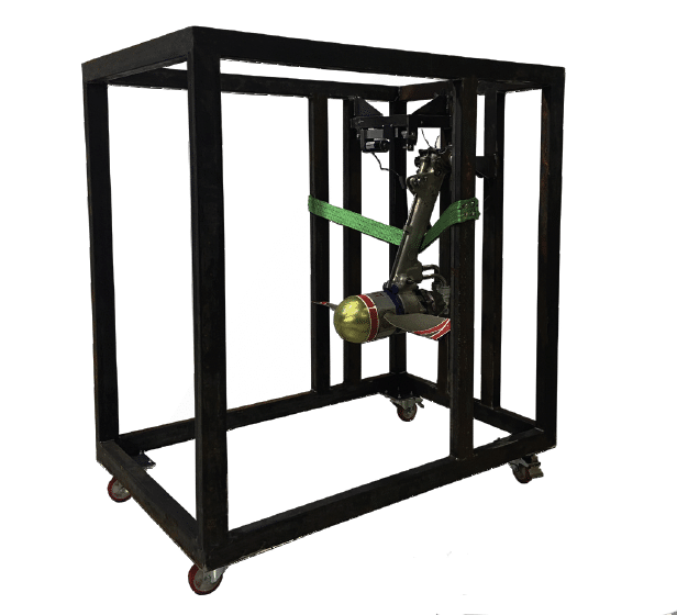
- Electromechanical Loads Generator Landing Gear Motor
- Cabin Air Blower
- Electromechanical Actuator Starter engine
Documentation and Power Specs
- User’s Manual
- Study Guide
- Instructor’s Guide
- Components Diagrams
- Flow Diagrams
- Electrical box
- Residual current device
- Emergency Button
- Energy Signal Lamp
- 110 VAC 60 Hz or 220-240 VAC 50 Hz


