Description
MAIN FEATURES:
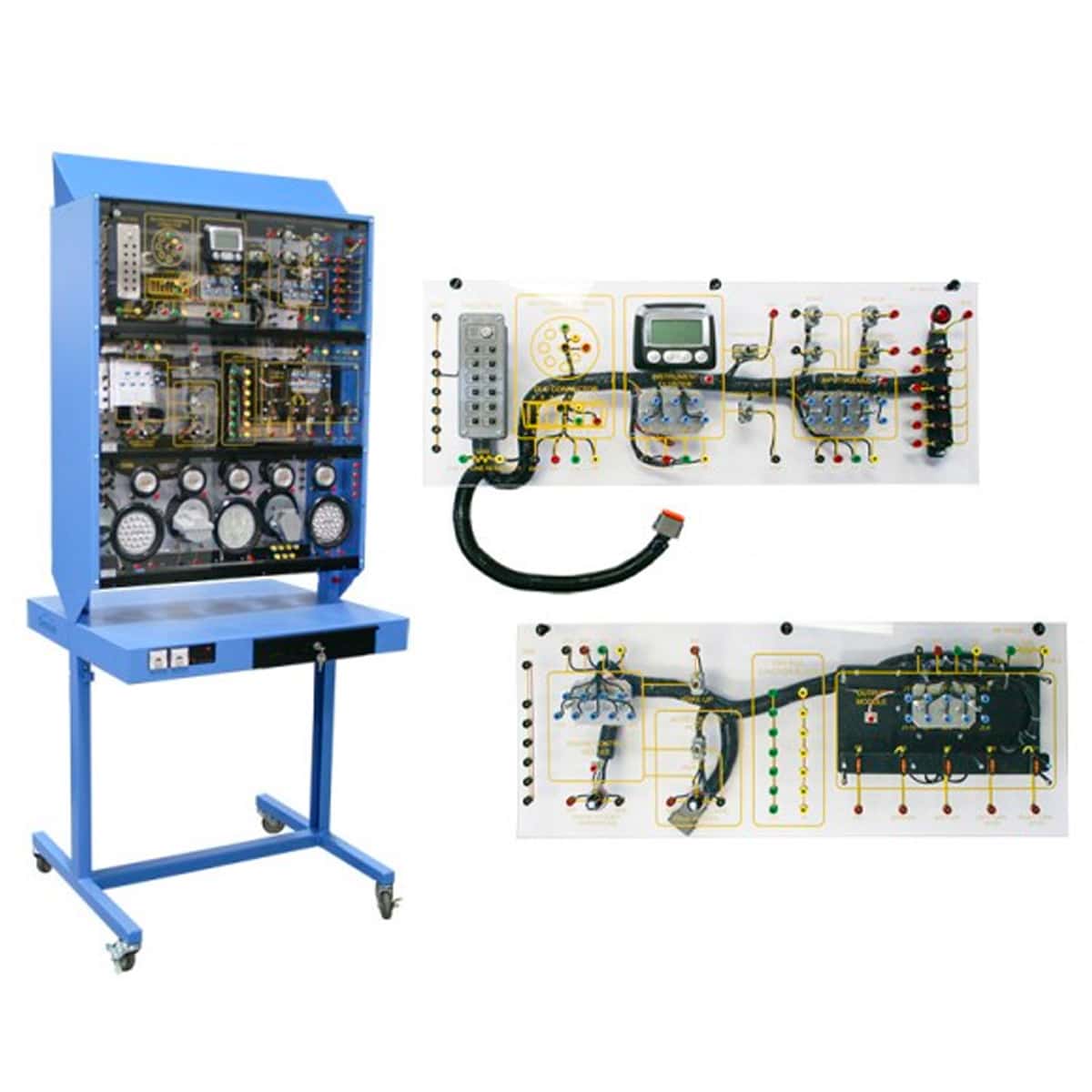
- Provides multiple student work stations accessible from either side
- Includes two (2) CAN Bus modules that replicates heavy vehicle applications (instrument cluster, input module, engine module and output module). The trainer can also be used to explain the basics of CAN-bus for automotive applications
- Demonstrates CAN Bus functions including: wake up mode, lighting controls, engine brake lighting controls, ECM signals and cluster display
- Includes analog/digital intputs and outputs
- Includes a J-1939 display that allows student to see system data changes in real time
- Trainer contains twelve (12) faults integrated into the system that address common issues affecting typical CAN Bus applications
- Each module has a breakout box with test points that allows student to troubleshoot the systems
- The system has a breakout box for J-1939 and data link connectors that allow students to install an oscilloscope to troubleshoot the signals
COMPONENTS/MODUPONENTS™ INCLUDED:
- One (1) MP-1918-01 Master Moduponent™ (53035)
- One (1) MP-1918-02 CAN Bus Moduponent™ (53036)
- One (1) MP-1918-13 Set of jumper leads (53052)
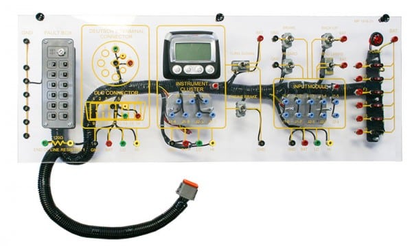
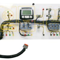
MODUPONENT (MP-1918-01) MASTER PANEL
- Electronic fault box with 12 integrated faults and connecter (keypad controlled with instructor key)
- Diagnostic test terminals
- Instrument cluster section
- Turn signal switch
- Brake switch
- Hazard switch
- Backup switch
- Headlamp switch
- Power indicator lamp
- Circuit fuses
- Input module section
- Engine brake mode switch
- End of line (termination resistor) #1
- Ground terminals (Black)
- Battery terminals (Red)
- CAN Bus LO terminals (Green)
- CAN Bus HI terminals (Yellow)
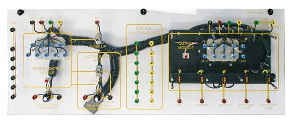
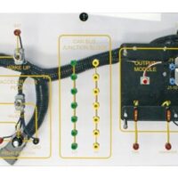
MODUPONENT (MP-1918-02) CAN Bus PANEL
- Engine control module section
- Accelerator pedal switch
- CAN Bus junction block
- Output module
- End of line (termination resistor) #2
- Ground terminals (Black)
- Battery terminals (Red)
- CAN Bus LO terminals (Green)
- CAN Bus HI terminals (Yellow)
- Fault box connecter

