Description
Features
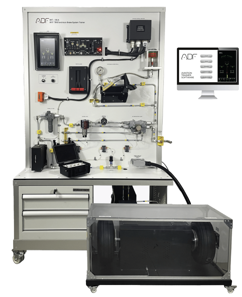
• Understanding fundamentals of aircraft auto-brake/anti-skid and its
components.
• Anti-skid and auto-brake system able to work together and independently
• Non operations of auto-brake scenario are implemented
• Operations of auto-brake scenario are implemented
• Take off scenario is implemented
• Landing scenario is implemented
• Auto-brake scenarios is implemented
• Rejected take off scenario is implemented
• Some of Trainer Functions
• Auto-brake function
• Anti-skid function
• Food brake function
• Rejected take off function
• WOW switch function
• Brake fan function
• Pumps fault function
• ECAM functions
• Single chime functions
• Master caution functions
• Master warning functions
Components
• Control Panel
• Aural warning horn
• Master warning resettable illuminated pushbutton
• Master caution resettable illuminated pushbutton
• Auto brake – low illuminated pushbutton
• Auto brake – medium illuminated pushbutton
• Auto brake – max illuminated pushbutton
• Auto brake – RTO illuminated pushbutton
• Auto brake – disarm instrument
• Anti-skid INOP instrument
• Brake fan control illuminated pushbutton
• Brake fan hot instrument
• Nose landing gear instrument light
• Left wing landing gear instrument light
• Right wing gear instrument light
• Landing gear unlock instrument light
• Hydraulic pump control illuminated pushbutton
• Hydraulic pump fault instrument light
• Three (3) aircraft circuit breaker
• Guarded master power switch
• Master power lamp
• Lockable Landing gear control lever
• AC engine on/off switch
• Air/ground switch
• Skid simulation panel
Training System Processes
• Take-off process
• Landing process
• Anti-skid fault process
• System test process
Training System Cases
• Brake hot
• Park brake fault
• Hydraulic fault
• Auto brake fault
• Instructor’s panel for Fault Insertion
• The system mounted on a metal/aluminum mobile stand.
• Metal/aluminum frame with 4 wheels. 2 of 4 wheels are lockable.
• Training video for teachers
• Delivered fully assembled tested and ready to operate
• Colored Ultraviolet printing method on aluminum composite panel• 10” inch screen (like EICAS or ECAM)
• Landing gear position
• Landing door position
• Numeric pressure value
• Sensor’s status
• Anti-Skid/Auto-Brake position status
• Numaric Simulated air speed value
• Electronic Control Box (Antiskid Control Computer)
• Antiskid Valve
• TQ – throttle quadrant
• Electrically Driven Hydraulic Pump
• Hydraulics Filter
• Hydraulic Fluid Reservoir
• Hydraulics tank Drain Valve
• Check valve
• Brake fan
• 0-100 bar Hydraulic System analog pressure gauge
• 0-100 bar Hydraulic System Pressure sensor
• Aircraft landing gear module
• Two(2) pieces Aircraft Tire
• Two(2) pieces Aircraft Wheel
• Two(2) pieces Aircraft Brake system
• Two(2) pieces AC motor for turning the wheels
• Plexiglass cover
• Aircraft foot Brake Pedal
• Aircraft foot Brake master cylinder
• Brake microswitch
• Two(2) pieces AC motor for turning the wheels
• Two(2) pieces AC motor driver
• Fault & instructor port
• Lockable Fault & instructor box
Documentation and Power Specs
• User’s Manual
• Study Guide
• Instructor’s Guide
• Components Diagrams
• Electrical box
• Residual current device
• Emergency Button
• Energy Signal Lamp
• 110 VAC 60 Hz or 220-240 VAC 50 Hz


