Description
Features
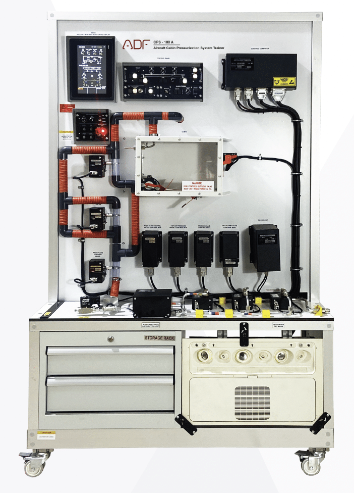
- Understanding fundamentals of aircraft Cabin Pressurization and its components.
- The training system is functional and configured like a typical aircraft Cabin Pressurization system.
- The trainer include the following panels that will work functionally.
- Aircraft Cabin Pressurization panel
- Aircraft air condition panel
- Aircraft auto-pilot panel
- Test panel
- Master power panel
- Master caution panel
- Two transparent cabin in the training set to simulate the interior of the cabin.
- 2 outflow valves, 1 negative pressure safety valve, and positive pressure safety valve (as a substitution) are in the transparent cabin.
- Out Flow Valves are engine controlled.
- The valves in the cabin pressurization system operate automatically during the take off and landing.
- Cabin pressurization valves are both controlled manually and automatically.
- The trainer is able to perform full automatic take off and landing.
- Indicators, panels and valves work simultaneously in landing and take-off simulations.
- Take off and landing simulations are controlled from the autopilot panel.
- Vertica speed and altitude are determined and selected during take-off and landing.
- Valve failures are easily observed on gauges and panels.
- PACK, BLEED, PACK FLOW and TEMPERATURE selections are made at the air condition panel.
- LDG elevation, MODE SELECT, MAN V/S CONTROL and DITCHING are done at the cabin pressurization.
- The selections made in the panels are visible on the screen.
- Wirings on the trainer are connected via terminals.
- Wires should have clear identification labels for each wire.
- All wires should be coded and labeled for troubleshooting.
- Instructor’s panel for Fault Insertion
- The system mounted on a metal/aluminum mobile stand.
- Metal/aluminum frame with 4 wheels. 2 of 4 wheels are lockable.
- Training video for teachers
- Delivered fully assembled tested and ready to operate
- Colored Ultraviolet printing method on aluminum composite panel
Components
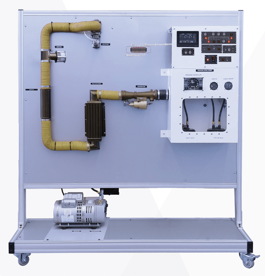
- Heat Exchanger
- Muffler
- Relief Valve
- Shut-Off Valve
- Vacuum Pump
- System Indicators
- PSU( Passenger Service Unit)
- 10 inch Lower ECAM
- Vertical speed indicator
- Altimeter indicator
- Cabin Altimeter
- Cabin pressure
- Air pressure
- Differential pressure
- Status area
- Flow status
- Pack flow status
- Bleed status
- Auto pilot status
- Pressurization mode
- Temp
- Air/ground
- Min 2 Outflow valve
- Min 2 outflow control computers
- Aircraft Cabin Pressurization panel
- Man V/S Control Switch
Component Technical Specs
- NAV/COMM Transceiver
- 200-channel NAV receiver
- Built-in VOR Converter
- Maksimum 25 kHz channel spacing
- Frequency(COM) 118.000 to 136.975
- Nav frequency 108.00 MHz to 117.95 MHz in 50 kHz spacing
- VOR/LOC converter
- Input voltage 28 VDC
- Built-in VOR/Localizer converter
- flip-flop frequencies
- Volume control
- Frequency memory and recall
- Display
- Frequency stability: ±0.0015%
- Original installation manual.


