Industrial Training from
MAP-200 SERIES
TABLETOP MATERIAL ASSEMBLY TRAINERS
PLC PROGRAMMING
& TROUBLESHOOTING


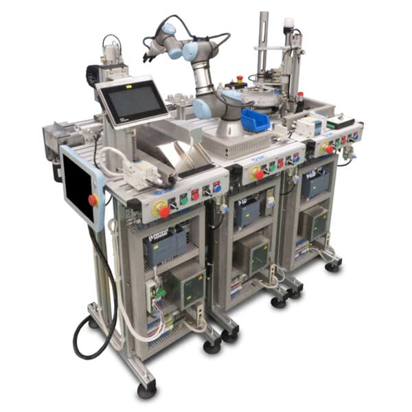
SMC’s MAP-200s consist of a series of individual tabletop mechatronics training systems that carry out a specific and different material handling task commonly seen in industrial settings.
Robust, Rugged, and Versatile, these tabletop hands-on training systems are designed to teach students a wide array of industrial automation – Pneumatics, Electrical, Industrial Safety and Automation Processes, PLC Programming, Sensors, and Troubleshooting!
MAP-202: Vacuum-Held Handling Device with Two Shafts
MAP-202: The function of this handling device is to transfer the part from a starting area to a final unloading area, using three vacuum pads. This is a cartesian handling device with two shafts which moves a part from one position to another, holding it with a set of three vacuum pads.
Pricing upon request

MAP-200 Body Supply Block

MAP-200 Bearing Insert Part

MAP-200 Shaft Insert Part

MAP-200 Cap Insert Part

Industrial Skills Made Accessible
Discover
INDUSTRIAL TECHNOLOGIES
From Industry, For Industry
SMC is the world's leading manufacturer of automation and pneumatic technologies for industry. Why not prepare your students on technologies that they will see in their future careers?
SKILLS-FOCUSED TRAINING
Competency-Based Learning
SMC training solutions are singularly focused on teaching the required skills of industry.
Our training solutions are aligned with the needs of industry, and designed to fit in the structure of modern classrooms.
DIGITAL TOOLS
Digital Simulations
Our award-winning simulation tools complement our hands-on training systems for robust training opportunities.
SMC eLearning guides students through automation and manufacturing concepts through interactive and engaging multimedia.
CREDENTIALS
CERTIFICATIONS
SMC Industrial Certification Pathways is the perfect credentialing tool for students to attain stackable industry-based certifications from manufacturing leaders.
With alignment and micro-certifications in areas such as Industry 4.0, Automation, Fluid Power, Mechanical, Process Control and Robotics pathways.
Industrial Technology and Automation Training Systems

From the Classroom to the Workforce
Industry's #1 Automation Manufacturer
SMC APPLIES ITS GLOBAL EXPERTISE IN INDUSTRIAL AUTOMATION AND ADVANCED MANUFACTURING TO CLASSROOM LEARNING ENVIRONMENTS WITH A COMPLETE PORTFOLIO OF AUTOMATION TRAINING SYSTEMS.
-
- Hands-on, Real-World Technologies that mirror the same technologies relied upon by leading industrial companies like Intel, Apple, Dell, Rockwell Automation, Boeing, and more.


Industry's #1 Automation Manufacturer
Forbes lists SMC as one of the top 1000 largest companies , as ranked by metrics such as Sales, Profits, Assets , and Market Value.
$36B+ and #1 in marketshare in the US and globally.
World's Best Employers
SMC is one of the best companies to work for according to an anonymous survey measuring employee satisfaction, economic impact , image, trust , gender equality, talent development , corporate social responsibility, culture, and benefits.
Most Innovative Companies
SMC was ranked #49th in a global survey of the most innovative companies, along with peers such as Apple, Google, Rockwell Automation, Siemens , etc.
SMC invests huge in R&D, and continues to forge an innovative and better path forward.
Industry Based Certifications
When schools care what certifications their students attain - that are not mere rubber-stamp certificates - and how marketable their students are for industry jobs, look no further than certifications from and for industry.
CUSTOMIZE YOUR INDUSTRIAL TRAINING PROGRAMS
We're here to help create the training program that fits with you school's and/or company's needs.
Our team of experts can perfectly align industry needs with student outcomes. And our industry-leading technology experts can craft the training system(s) to meet your needs, budget, and space requirements.

Suitcase Technology Trainers

Tabletop Trainers
")
Tabletop Training Systems

Integrated Systems Trainers

Complete Factory Systems
See how toolkit can help your program
Reach out to our sales team to see which Tenstar configuration would best serve your education or training program!
Sales
sales@toolkittech.com
(512) 203-0590
General
info@toolkittech.com
"*" indicates required fields