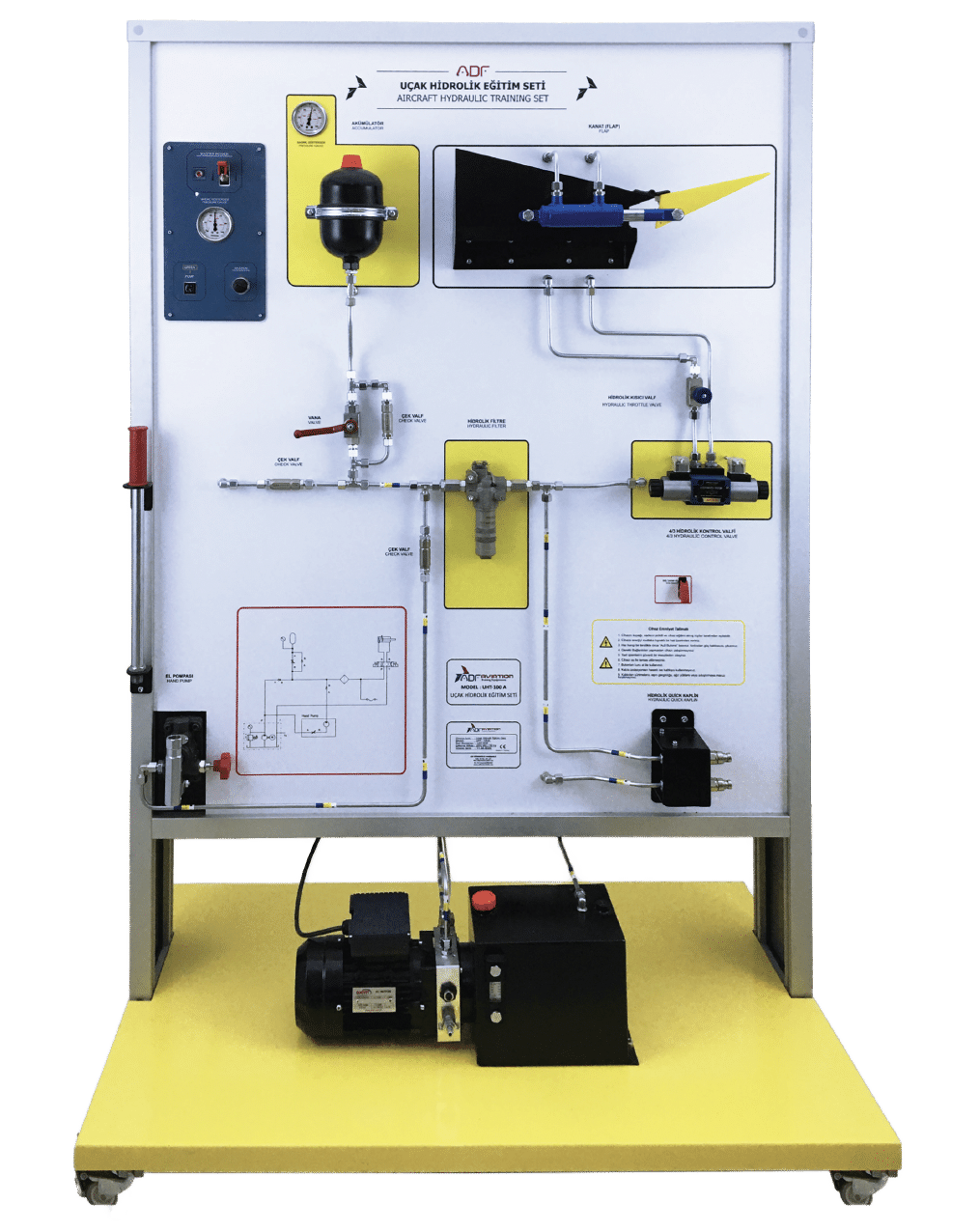
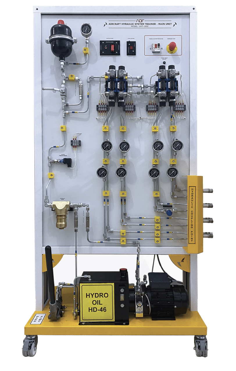
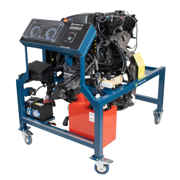
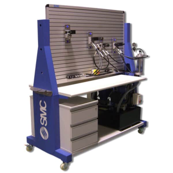
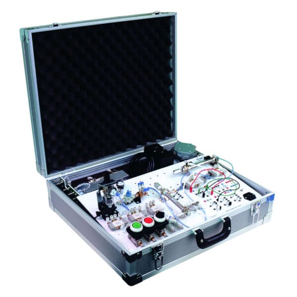
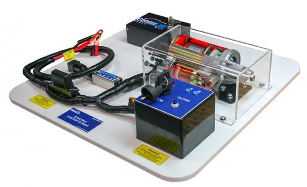
Toolkit Technologies’ Aviation Hydraulics Training System provides students with the practical experience needed to understand the function and role of hydraulic systems in modern aircraft.
Students will get to know hydraulic components and improve troubleshooting skills on real-world, industrial technologies that mirror industrial applications.
The training system is comprised of a fully functional hydraulic system designed so that every component can be disassembled, reassembled and functionally tested.
All the components mounted on the trainer are operational, removable and they can be reinstalled.
NOTE:
Aircraft Hydraulic System Trainer provides students with practical experience needed to understand the function, to get to know components and to improve troubleshooting skills. Fully functional hydraulic system designed so that every component can be disassembled, reassembled and functionally tested.
All the components mounted on the trainer are operational, removable and they can be reinstalled.
NOTE: The EICAS/ECAM screen is located on the hydraulic landing gear trainer or main unit, which can be connected to this system.


